Featured products
General-purpose vector inverter with a very wide power range and upgraded DSP — high speed accuracy and torque response, output frequency up to 3200 Hz.
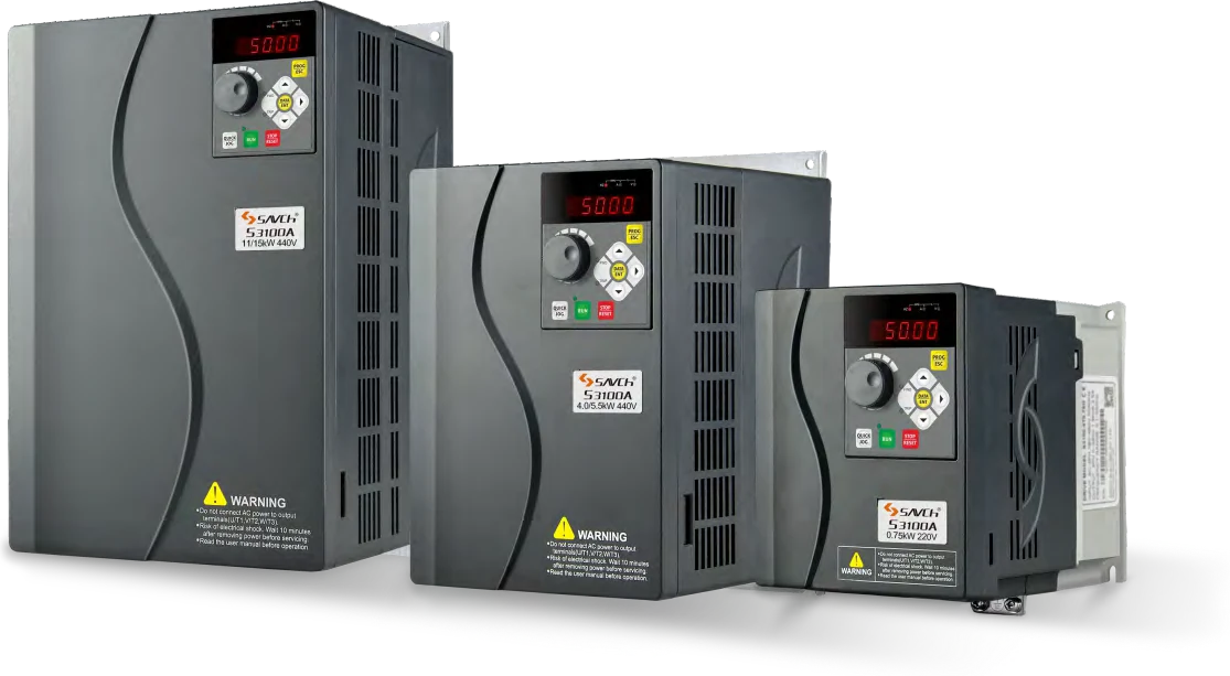
S3100A/E series is an upgraded version of the S3100 series inverter. The original high hardware configuration remains unchanged, the operation mode is adjusted to real usage habits, and the driver performance together with the bottom and application software layers are improved.
Multi terminal ports
| Terminal | Function |
|---|---|
| AVI | DC 0 ~ +10 V input |
| AVI2 / ACI | DC 0 ~ +10 V / DC 4 ~ 20 mA |
| MI5 | Pulse input |
| AFM | Analog output |
| DFM | Pulse output |
| Item | Explanation | |
|---|---|---|
| Control characteristic | Control mode | V/f control, open loop vector control, torque control |
| Range of output frequency | 0 ~ 500.00 Hz (V/f highest 3200.0 Hz) | |
| Frequency setting resolution | 0.01 Hz | |
| Output frequency setting resolution | 0.01 Hz | |
| PWM carrier frequency | Adjust from 0.5 kHz to 16 kHz | |
| Torque boost | Open loop vector control (SVC): G type 0.5 Hz / 150 %, P type 0.5 Hz / 120 % | |
| V/f curve | Three types: line, multi-point, Nth power V/f curve(1.2th, 1.4th, 1.6th, 1.8th, 2th power) | |
| V/f separation | Two types: full separation, semi-separation | |
| Jump frequency | Adjust from 0.1 Hz to 500.00 Hz | |
| Acceleration / deceleration time | 0.00 to 65000 seconds (4-stage acceleration/deceleration time is set independently), linear or S-curve acceleration/deceleration mode | |
| Over current stall prevention level | Can be set according to the motor load characteristics with 100 ~ 200 % of the rated current of the driver | |
| DC brake | When stopping, it can be operated from 0.00 to the maximum operating frequency, and the braking current is 0 to 100 % of the rated current. Start time 0 ~ 100.0 seconds, stop time 0 ~ 100.0 seconds. | |
| Brake torque | 20 % (external optional brake resistor can reach 125 %)(1 ~ 50 HP brake transistor built-in, 60 HP and above can be connected to the external brake unit module) | |
| Speed ratio | Open loop vector control: 1 : 100 | |
| Operation characteristic | Frequency setting signal — keypad | Set by the ▲ ▼ keys |
| Frequency setting signal — external terminal | DC 0 ~ 10 V, DC 4 ~ 20 mA, serial communication (RS485) | |
| Operation signal — keypad | Available to be operated by RUN, STOP, JOG keys | |
| Operation signal — external terminal | 2-wire / 3-wire operation, jog operation, serial communication (RS485) | |
| Input terminal of multi-function | Forward and reverse running, three-wire running control, forward and reverse jog running, free stop, reset fault, running pause, external fault input, increment/decrement frequency terminal setting, 16-segment preset speed switching, acceleration/deceleration time switching, frequency source switching, running command switching, PID control, PLC status reset, pause swing frequency, reset swing frequency, prohibit acceleration and deceleration, disable torque control, calculator function, length count, frequency increase and decrease setting clear, high speed pulse frequency, stop DC braking, frequency modification enable, speed control and torque control switching, clear running time of this time. | |
| Output terminal of multi-function | Inverter operation, fault output, frequency level detection FDT output, frequency arrival, zero speed operation, overload pre-alarm, count value arrival, length arrival, PLC cycle completion, cumulative running time arrival, frequency limitation, torque limit, ready to run, AVI1 > AVI2, upper limit frequency arrival, lower limit frequency arrival (operation related), undervoltage status output, communication setting, cumulative power-on time arrival, frequency arrival output, timing arrival output, offload, reverse in operation, zero current state, module temperature reached, output current exceeds the limit, lower limit frequency arrival (also output on stop), alarm output (continues to run), and running time arrival. | |
| Analog signal output | Corresponding to the actual output frequency, output current, output voltage, etc. | |
| Fault signal contact | Contact "ON" (one "C" contact relay or two open collector outputs when the AC drive fails) | |
| Inner function | Output frequency upper and lower limit setting, instantaneous power failure restart, abnormal fault restart, speed tracking, simple PLC, multi-speed operation, PID control, timing control, automatic regulated output regulation, abnormal record, parameter lock, parameter factory reset, reverse rotation prohibited, overcurrent stall prevention, overvoltage stall prevention, electronic thermal relay. | |
| Protection function | Short circuit protection, acceleration over current, deceleration over current, constant speed over current, acceleration over voltage, deceleration over voltage, constant speed over voltage, bus undervoltage fault, motor overload, inverter overload, over torque protection, loss phase on the input (7.5G/11P and above), loss phase on the output, module overheating, external fault, communication fault, current detection fault, motor self-learning fault, parameter read and write abnormality, inverter hardware abnormality, motor short circuit to ground, running time arrival, power-on time arrival, load dropped, PID feedback disconnected, and fast current limit timeout. | |
| Number of part on keypad | Contains 8 function keys, a 5-digit 8-segment LED display and 6 status indicator LEDs. Can set the frequency, display the actual output frequency, output current and user-defined unit; parameter browsing and modification, parameter locking, abnormal fault display; run, stop, reset, forward/reverse and jogging. | |
| Environment | Operation temperature | −10 °C ~ +40 °C |
| Temperature of stock | −20 °C ~ +60 °C | |
| Humidity of operation environment | Below 90 % RH, no condensation | |
| Height of installation | No more than 1000 m in height, no corrosive gas, liquid, dust | |
| Vibration | Below 20 Hz 9.80665 m/s² (1 G), 20 ~ 50 Hz 5.88 m/s² (0.6 G) | |
| Enclosure | IP20 (depending on the end customer's installation environment) | |
220 V single phase / three phase series
| Item | Specifications | |||||||
|---|---|---|---|---|---|---|---|---|
| S3100A/E-2T***G | 0.4 | 0.75 | 1.5 | 2.2 | 4.0 | 5.5 | 7.5 | |
| Output | Max. applicable motor output power(kW) | 0.4 | 0.75 | 1.5 | 2.2 | 4.0 | 5.5 | 7.5 |
| Max. applicable motor output power(HP) | 0.5 | 1 | 2 | 3 | 5.4 | 7.4 | 10 | |
| Output rated capacity(kVA) | 1.1 | 1.5 | 2.7 | 3.7 | 6.5 | 9.5 | 12.2 | |
| Output rated current(A) | 2.3 | 4.0 | 7.0 | 9.6 | 17.0 | 25 | 32 | |
| Output frequency range | 0 ~ 500 Hz | |||||||
| Overload capacity | 150 % — 60 s | |||||||
| Max output voltage | Same as input voltage | |||||||
| Input | Phase, voltage, frequency | Single phase / three phase 200 ~ 240 V · 50/60 Hz | ||||||
| Voltage & frequency variations | Voltage ±15 %, frequency ±5 % | |||||||
| Input current — single phase(A) | 5.4 | 8.2 | 14.2 | 23 | No single phase input | |||
| Input current — three phase(A) | 3.1 | 5.0 | 7.7 | 11.1 | 22.2 | 31.5 | 42.7 | |
| Cooling method | Fan cooling | |||||||
440 V three phase series · 0.75 ~ 55 kW
| Item | Specifications | ||||||||||||||
|---|---|---|---|---|---|---|---|---|---|---|---|---|---|---|---|
| S3100A/E-4T***G/P | 0.75 | 1.5 | 2.2 | 4.0 | 5.5 | 7.5 | 11 | 15 | 18.5 | 22 | 30 | 37 | 45 | 55 | |
| Output | Max. applicable motor output power(kW) | 0.75 | 1.5 | 2.2 | 4.0 | 5.5 | 7.5 | 11 | 15 | 18.5 | 22 | 30 | 37 | 45 | 55 |
| Max. applicable motor output power(HP) | 1 | 2 | 3 | 5.4 | 7.4 | 10 | 14.7 | 20 | 24.7 | 29.4 | 40 | 50 | 60 | 74 | |
| Output rated capacity(kVA) | 1.9 | 2.9 | 3.9 | 6.9 | 9.9 | 13 | 19.1 | 24.4 | 28.2 | 34.3 | 45.7 | 57.1 | 68.6 | 83.8 | |
| Output rated current(A) | 2.5 (3.2) | 3.8 (4.7) | 5.1 (6.5) | 9 (11.8) | 13 (15) | 17 (21.7) | 25 (28.5) | 32 (35.4) | 37 (42) | 45 (60) | 60 (75) | 75 (85) | 90 (110) | 110 (152) | |
| Output frequency range | 0 ~ 500 Hz | ||||||||||||||
| Overload capacity | G: 150 % — 60 s · P: 120 % — 60 s | ||||||||||||||
| Max output voltage | Same as input voltage | ||||||||||||||
| Input | Phase, voltage, frequency | Three phase 380 ~ 460 V · 50/60 Hz | |||||||||||||
| Voltage & frequency variations | Voltage ±15 %, frequency ±5 % | ||||||||||||||
| Input current(A) | 3.4 | 5.0 | 5.8 | 10.5 | 15 | 20.5 | 26 | 35 | 38 | 46 | 62 | 76 | 92 | 113 | |
| Cooling method | Fan cooling | ||||||||||||||
440 V three phase series · 75 ~ 250 kW
| Item | Specifications | |||||||||
|---|---|---|---|---|---|---|---|---|---|---|
| S3100A/E-4T***G/P | 75 | 90 | 110 | 132 | 160 | 185 | 200 | 220 | 250 | |
| Output | Max. applicable motor output power(kW) | 75 | 90 | 110 | 132 | 160 | 185 | 200 | 220 | 250 |
| Max. applicable motor output power(HP) | 100 | 120 | 147 | 176 | 214 | 247 | 267 | 294 | 334 | |
| Output rated capacity(kVA) | 114.3 | 134 | 160 | 191 | 229 | 259 | 290 | 316 | 358 | |
| Output rated current(A) | 152 (176) | 176 (210) | 210 (253) | 253 (304) | 304 (340) | 340 (377) | 377 (426) | 426 (465) | 465 (520) | |
| Output frequency range | 0 ~ 500 Hz | |||||||||
| Overload capacity | G: 150 % — 60 s · P: 120 % — 60 s | |||||||||
| Max output voltage | Same as input voltage | |||||||||
| Input | Phase, voltage, frequency | Three phase 380 ~ 460 V · 50/60 Hz | ||||||||
| Voltage & frequency variations | Voltage ±15 %, frequency ±5 % | |||||||||
| Input current(A) | 157 | 180 | 214 | 256 | 308 | 345 | 382 | 430 | 470 | |
| Cooling method | Fan cooling | |||||||||
440 V three phase series · 280 ~ 800 kW
| Item | Specifications | ||||||||||
|---|---|---|---|---|---|---|---|---|---|---|---|
| S3100A/E-4T***G/P | 280 | 315 | 355 | 400 | 450 | 500 | 560 | 630 | 710 | 800 | |
| Output | Max. applicable motor output power(kW) | 280 | 315 | 355 | 400 | 450 | 500 | 560 | 630 | 710 | 800 |
| Max. applicable motor output power(HP) | 374 | 420 | 470 | 530 | 600 | 660 | 755 | 840 | 1031 | 1172 | |
| Output rated capacity(kVA) | 396 | 445 | 500 | 565 | 630 | 700 | 785 | 871 | 1006 | 1143 | |
| Output rated current(A) | 520 (585) | 585 (650) | 650 (725) | 725 (820) | 820 (860) | 860 | 1040 | 1180 | 1320 | 1500 | |
| Output frequency range | 0 ~ 500 Hz | ||||||||||
| Overload capacity | G: 150 % — 60 s · P: 120 % — 60 s | ||||||||||
| Max output voltage | Same as input voltage | ||||||||||
| Input | Phase, voltage, frequency | Three phase 380 ~ 460 V · 50/60 Hz | |||||||||
| Voltage & frequency variations | Voltage ±15 %, frequency ±5 % | ||||||||||
| Input current(A) | 525 | 590 | 655 | 730 | 825 | 865 | 1045 | 1185 | 1452 | 1650 | |
| Cooling method | Fan cooling | ||||||||||
| Fig. | Inverter type | W | W1 | W2 | H | H1 | D | M | N |
|---|---|---|---|---|---|---|---|---|---|
| Size 1 | S3100A/E-2T0.4G2T0.75G2T1.5G4T0.75G/1.5P4T1.5G/2.2P4T2.2G/4.0P | 108 | 94 | 94 | 138.1 | 118 | 159.5 | 5 | 5 |
| Size 2 | S3100A/E-2T2.2G2T4.0G4T4.0G/5.5P4T5.5G/7.5P4T7.5G | 130 | 108 | 108 | 209 | 198 | 169.8 | 5 | 5 |
| Size 3 | S3100A/E-4T7.5G/11P4T11G/15P4T15G | 140 | 122 | 122 | 260 | 248 | 176.6 | 6 | 6 |
| Size 4 | S3100A/E-2T5.5G2T7.5G4T15G/18.5P4T18.5G/22P4T22G | 180 | 160 | 160 | 298 | 284 | 180 | 6.5 | 6.5 |
| Size 5 | S3100A/E-2T11G2T15G2T18.5G4T22G/30P4T30G/37P4T37G/45P | 260 | 176 | 176 | 412 | 397.5 | 203 | 6.5 | 13 |
| Size 6 | S3100A/E-2T22G4T45G/55P | 305 | 160 | — | 460 | 442 | 243 | 7 | 14 |
| Size 7 | S3100A/E-2T30G2T37G2T45G2T55G4T55G/75P4T75G/90P4T90G/110P4T110G | 320 | 160 | 230 | 580 | 563 | 280 | 9 | 17 |
| Size 8 | S3100A/E-4T110G/132P4T132G/160P4T160G | 380 | 160 | — | 724.2 | 694 | 330.5 | 12 | 22 |
| Size 9 | S3100A/E-4T185G/200P4T200G/220P | 450 | 160 | 160 | 780 | 746 | 385 | 12 | 25 |
| Size 10 | S3100A/E-4T220G/250P4T250G/280P4T280G/315P4T315G | 500 | 190 | 190 | 882 | 849 | 414 | 13 | 25 |
| Size 11 | S3100A/E-4T315G/355P4T355G/400P4T400G/450P | 626 | 250 | — | 982 | 949 | 408 | 13 | 25 |
| Size 12 | S3100A/E-4T450G/500P4T500G | 737 | 250 | — | 982 | 947 | 413 | 13 | 25 |
| Size 13 | S3100A/E-4T560G4T630G | 1000 | — | — | 2155 | — | 800 | — | — |
| Size 14 | S3100A/E-4T710G4T800G | 1220 | — | — | 2179 | — | 760 | — | — |
Remarks
Description of terminal function
| Terminal NO. | Terminal name | Function | Parameter |
|---|---|---|---|
| TB5 | AFM1-ACM analog output 1 | 1. Output current specification: 0 ~ 20 mA. 2. AFM1 and AFM on the control board are the same signal source. | 06-07 |
| TB5 | AFM2-ACM analog output 2 (select voltage or current output by jumper J2) | 1. Output voltage specification: DC 0 ~ +10 V. 2. Output current specification: 0 ~ 20 mA. | 06-08 |
| TB6 | MA-MB-MC relay contact output | 1. Normally open MA-MC, normally closed MB-MC. 2. Contact: AC 125 V 0.5 A, DC 30 V 2 A. | 06-02 |
Description of terminal function
| Terminal NO. | Terminal name | Function | Parameter |
|---|---|---|---|
| TB1 | AFM1-ACM analog output 1 (select voltage or current output by jumper J1) | 1. Output voltage specification: DC 0 ~ +10 V. 2. Output current specification: 0 ~ 20 mA. 3. AFM1 and AFM on the control board are the same signal source. | 06-07 |
| TB1 | AFM2-ACM analog output 2 (select voltage or current output by jumper J2) | 1. Output voltage specification: DC 0 ~ +10 V. 2. Output current specification: 0 ~ 20 mA. | 06-08 |
| TB2 | MA-MB-MC relay contact output | 1. Normally open MA-MC, normally closed MB-MC. 2. Contact: AC 250 V 3 A, DC 30 V 3 A. | 06-02 |
Send us the load, voltage and application — QS engineering helps pick the model code, cable and matching accessories.